




How to Install a Display Driver Board in an iMac 27" 5K (2014–2020)
Give your retired iMac 27" 5K a new life as a stunning 5K external monitor. This guide walks you through removing the internal components, installing the Macfixit 5K Display Driver Board, and connecting it to any Mac or PC via USB-C.


What’s in the Kit
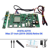
- 5K LCD Display Driver Board
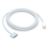
- USB-C cable
- Display adhesive cutter
- Replacement display adhesive strips
- Power adapter
Tools You’ll Need
- T8 & T10 Torx screwdrivers
- Large flat-head screwdriver
- Plastic pry tool / spudger
- Double-sided foam tape
- Anti-static wrist strap (recommended)
- Soft cloth or foam mat
Part 1
Disassembly
Confirm your iMac model & prepare your workspace
Confirm you have an iMac 27-inch (2014–2020) — check the label on the bottom of the stand. Place the iMac screen-down on a soft surface like a folded towel or foam pad to protect the glass. Have your tools ready before starting.
Disconnect the power line

Cut the display adhesive with the pizza slicer tool

Insert the included display adhesive cutter (pizza slicer) into the gap between the glass panel and the aluminium frame. Work slowly around the entire perimeter to slice through the adhesive tape that secures the display.
Slowly open the screen — cables are still connected

Carefully begin to lift the display panel. Do not pull it fully open — the screen is still attached by the power cable and the display data (flex) cable. Support the glass with one hand and stop once you have enough room to reach the connectors.
Disconnect the power cable first

Disconnect the power cable before the display cable. Locate the power connector (a flat multi-pin socket near the centre of the chassis) and unplug it. This eliminates residual charge from the capacitors and makes subsequent steps safer.
Disconnect the display cable


Locate the display data cable connector on the logic board. Lift the small locking tab, then carefully pull the cable straight out. Handle it gently — this eDP cable will be reused with the driver board.
Fully open the screen and remove remaining adhesive


With the cables free, open the display fully or lift it away from the chassis. Using a plastic pry tool, peel off all remaining adhesive strips from around the frame. Clean adhesive on the rim is important for a good seal when reassembling.
Screen is removed

The display panel is now completely removed. Set it aside face-down on a clean, soft surface to protect the glass. The iMac chassis is now open and ready for internal component removal.
Unscrew the screen bracket strip

Using a Philips or flip-head screwdriver, remove the screws securing the screen bracket strip on the screen side. This releases the assembly which you will connect to the driver board later.
Loosen (or remove) the speakers


Use a T10 Torx screwdriver to loosen the speaker mounting screws. You do not need to remove them completely — just making them loose gives you more room to manoeuvre during logic board removal. Removing the speakers entirely is optional — your choice.
Remove the fan

Disconnect the fan power connector and remove the fan mounting screws. Lift the fan straight out. The fan is no longer needed once the internal components are removed.
Remove the power supply

Disconnect all cables running to the power supply unit. Unscrew the mounting screws and carefully lift the PSU out of the chassis — it is heavy. Set it aside. The original power supply is not reused in this build.
Unscrew the main logic board


Locate all logic board mounting screws (typically 6–8 screws). Use T8 and T10 Torx screwdrivers. Work methodically around the board and keep the screws in a safe place. Do not remove the board yet — disconnect the cables first (next step).
Disconnect all connectors from the logic board


Carefully disconnect every remaining cable from the logic board — lift locking tabs first, then pull each connector straight out. Include all power, antenna, and ribbon cables. Once all connectors are free, lift the logic board out of the chassis.
Unscrew and remove the Wi-Fi antenna


Unscrew the Wi-Fi antenna card mounting screws and gently peel the antenna away from the chassis. The antenna cables are very thin and fragile — handle with care and do not yank the wires.
Remove remaining screws and extract the power socket


Remove any remaining screws in the chassis. Then locate the power socket on the rear of the iMac — remove the two small screws holding it in place. Use a large flat-head screwdriver to push the socket from inside the chassis, pushing firmly downward until it pops out through the rear panel. You will now see a clean rectangular hole where the power socket was — this is where the USB-C and power cables will exit.
Clean the chassis and apply new adhesive


Clean the inside and rim of the iMac chassis if needed, removing any dust or debris. Apply the supplied adhesive strips around the rim. Keep the plastic backing film on for now — you will peel it just before pressing the glass back down.
Remove old adhesive from the display panel

Using a plastic pry tool, carefully peel all remaining adhesive from the edges of the glass panel. The surface must be completely clean for the new adhesive strips to bond properly during reassembly.
Remove the display cable from the panel


Gently disconnect the eDP display cable from the back of the LCD panel. Lift the locking tab and pull the connector straight out. This cable will connect to the driver board in Part 2.
Part 2
Driver Board Installation
Apply Kapton tape to the display panel

Before connecting the driver board, apply Kapton tape over the exposed metal areas on the back of the LCD panel near the connector. This insulating tape prevents short circuits between the board electronics and the bare metal of the panel.
Connect the display cable to the driver board


Carefully align the eDP display cable with the connector on the driver board. Press it flat until it seats fully and the locking tab engages. Give it a gentle tug to confirm it is locked in — a loose connection will cause a blank or flickering screen.
Connect the power cable — holes facing up


Connect the power cable to the driver board. Look for the two small holes on the connector housing — ensure those two holes are facing upward before inserting. The correct orientation is also marked on the board itself. Incorrect polarity will prevent the display from powering on.
Complete the installation — connect USB-C and power


The driver board is now fully connected. Route the USB-C video cable and power adapter cable through the hole left by the removed power socket. These cables will remain external — connecting to your computer and wall outlet respectively.
Mount the controller board and power supply


Use double-sided tape to mount the controller board securely inside the rear of the iMac chassis — this gives easy access to the USB-C and power ports. The board is safe to touch during normal operation. Attach the power supply brick to the back of the iMac stand using additional double-sided tape. You can choose your own preferred mounting location for the power supply.
Part 3
Testing & Reassembly
Test the display before sealing

Before sealing the glass, run a full test. Connect the USB-C cable to your MacBook or computer and plug in the power adapter. The iMac panel should light up and show your computer’s screen at full 5K resolution. The adhesive plastic film has not been removed yet at this stage — test everything first.
Seal the display

Once confirmed working, peel the plastic backing film from the adhesive strips around the rim. Carefully lower the glass panel back onto the chassis, aligning it evenly on all sides. Press firmly around the entire perimeter to bond the adhesive. Hold for 30–60 seconds to ensure good adhesion.
Part 4
Language & Settings
Change the OSD language to English (if needed)

If the on-screen display (OSD) menu appears in a non-English language, use this button sequence to switch to English:
Menu → Down (6×) → Menu (3×)
Adjust colour settings (optional)

The driver board’s OSD menu includes colour temperature and brightness adjustments. These are entirely optional — explore the menu to find the settings that suit your preference and viewing environment.
Understanding button orientation

The Up and Down OSD navigation buttons work relative to the physical orientation of the controller board. If your Up/Down navigation seems reversed, rotate the board 180° and remount it. The words “Up” and “Down” are printed directly on the board as a reference.
Reference
Troubleshooting
| Issue | Likely Cause | Solution |
|---|---|---|
| No image on screen | Loose eDP or power cable | Re-seat the eDP cable at both ends |
| Monitor not detected | USB-C port lacks DisplayPort Alt Mode | Try a Thunderbolt / USB4 port |
| Screen flickers | Loose power connection | Check the DC barrel connector on the board |
| Very dim image | Backlight cable not seated | Re-seat the backlight power connector |
| Resolution lower than 5K | Host port bandwidth limitation | Use a Thunderbolt 3/4 or USB4 port for full 5K |
| OSD buttons inverted | Board mounted upside down | Rotate the controller board 180° and remount |
| OSD in non-English language | Default language setting | Follow Step 27 above |
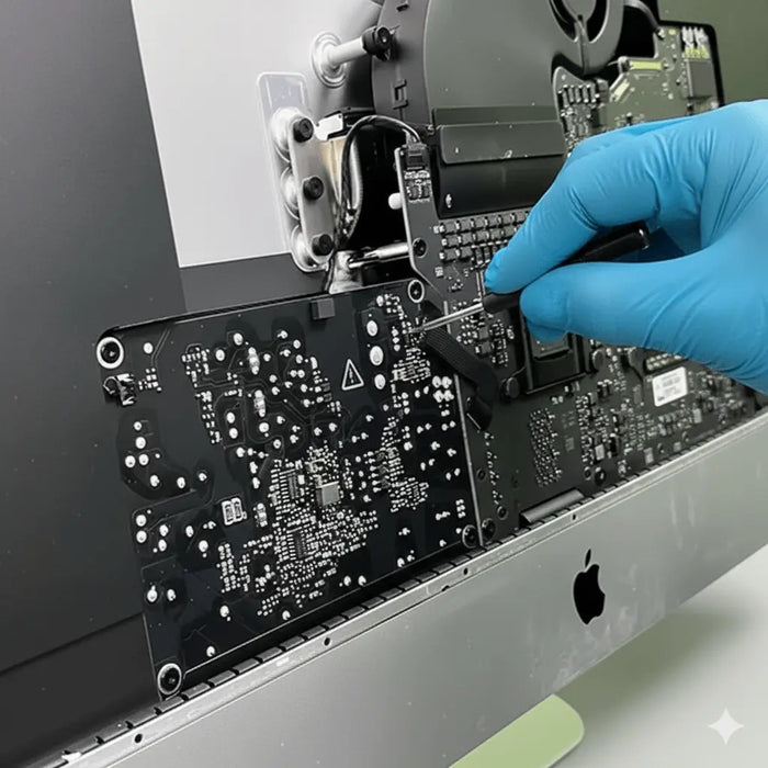
Our certified technicians at Macfixit Australia can install your iMac 27" Display Driver Board for you. Drop in at our Balwyn, VIC workshop for an in-person service, or ship your iMac to us from anywhere in Australia — we’ll handle the full installation, test it, and ship it straight back to you. A shipping fee applies. Installed and tested within 1–2 business days.
View Installation Service →Installation Complete!
Your iMac 27" (2014–2020) is now a fully functional 5K external monitor. Camera and speakers are no longer active — but the display looks absolutely stunning.
Buy the 5K Display Driver Board →Questions? Email us at helpdesk@macfixit.com.au
Important: where to place the double-sided tape
When you mount the driver board, the double-sided foam tape must only touch a bare, flat area of the board. If the tape is placed over the pin headers, solder pads or components, it can bridge the contacts and cause a short circuit — which can permanently damage the board. Take a moment to position the tape correctly before pressing it down.


The board pictured is a sample from our workshop — yours may look slightly different depending on your model, but the same rule applies to every board: keep the tape clear of pins, solder pads and components.