




How to Install a Display Driver Board in an iMac 27" (2012–2013)
Give your retired iMac 27" a new life as a stunning 2K external monitor. This guide walks you through removing the internal components, installing the Macfixit Display Driver Board, and connecting it to any Mac or PC via USB-C.


What's in the Kit
- LCD Display Driver Board
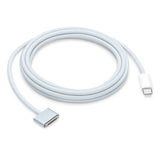
- USB-C cable
- Display adhesive cutter
- Replacement display adhesive strips
- Power adapter
Tools You'll Need
- T8 & T10 Torx screwdrivers
- Plastic pry tool / spudger
- Double-sided tape
- Anti-static wrist strap (recommended)
- Soft cloth or foam mat
Part 1
Disassembly
Confirm your iMac model
Confirm you have an iMac 27" (2012–2013) — check the label on the bottom of the stand. Place the iMac screen-down on a soft surface like a towel or foam pad to protect the glass.
Cut the display adhesive

Using the included display adhesive cutter, carefully slice through the adhesive tape around the entire perimeter of the glass. Apple used adhesive to secure the front display panel on these models — work all the way around before lifting.
Lift the display and disconnect the cables


Gently lift the display panel — do not pull it too far yet, as it is still connected by two cables. Disconnect the display data cable (eDP connector) and the backlight power cable. Once disconnected, carefully set the display panel aside — this is the panel you will reuse as your new monitor.
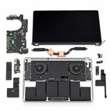
Remove internal components


Remove all internal hardware that is no longer needed:
- Hard drive and its bracket
- Power supply unit
- Cooling fans
- Logic board (motherboard)
- Speakers (optional)
Use T8 and T10 Torx screwdrivers. Keep track of your screws and remove cables gently to avoid damaging the frame. Speakers can remain if they do not interfere with mounting.
Part 2
Driver Board Installation
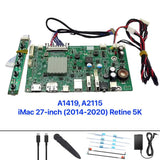
Understand the driver board connections

Before installing, familiarise yourself with the driver board ports. The board has an eDP connector for the display data cable, a backlight power socket, a USB-C input, and a DC power jack. All four connections must be made for the display to function correctly.
Connect the eDP cable to the LCD panel

Connect the eDP cable from the driver board to the LCD panel's display connector. Align carefully and press the connector flat — it locks with a small tab. Give it a gentle tug to confirm it is fully seated.
Connect the backlight power cable


Connect the backlight power cable from the driver board to the panel socket. Both the eDP and backlight connections are essential — without either, the panel will not function.
Connect the USB-C and power cables to the board
Connect the USB-C cable and power cable to the circuit board. These will be routed out of the chassis in the next step. Do not power on yet.
Route cables through the RAM slot
Use the empty RAM slot opening at the back of the iMac chassis to route the USB-C and power cables cleanly out of the unit. This keeps the cable run tidy and accessible once the display is reassembled.
Mount the controller board

Use double-sided tape to secure the display driver board inside the iMac housing. Mount the controller board at the back of the chassis for easy access to the USB-C and power ports.
Part 3
Testing & Reassembly
Test the display before reassembling
Before closing the unit, run a test:
- Connect the controller board to your computer using the USB-C cable.
- Plug in the power supply and turn the display on.
- Use the OSD buttons to select the correct input if needed.
If everything is connected correctly, the iMac panel should power up and show your computer's display.
Clean up and reassemble

Once confirmed working:
- Route all wires neatly inside the chassis using cable ties where needed.
- Secure the controller board and OSD button board with double-sided tape.
- Reattach the glass panel using the supplied adhesive strips.
Your iMac 27" is now a fully functional high-quality external monitor. Note: the USB-C cable and power adapter will remain outside the iMac.
Part 4
Language Setup
Change the OSD language to English (if needed)


If the OSD menu appears in a non-English language, use the following sequence to switch to English:
Menu → Down (6 times) → Menu (3 times)
After completing this, the menu language will be set to English.
Reference
Troubleshooting
| Issue | Likely Cause | Solution |
|---|---|---|
| No image on screen | Loose eDP or power cable | Re-seat the eDP cable at both ends |
| Monitor not detected | Wrong USB-C input selected | Press input button on OSD to cycle to USB-C |
| Screen flickers | Loose power connection | Check the DC barrel connector on the board |
| Very dim image | Backlight cable not seated | Re-seat the backlight power connector |
| OSD in non-English language | Default language setting | Follow Step 13 above |
Installation Complete!
Your iMac 27" (2012–2013) is now a fully functional 2K external monitor. Camera and speakers are no longer active — but the display looks incredible.
Buy the Display Driver Board →Questions? Email us at helpdesk@macfixit.com.au
Important: where to place the double-sided tape
When you mount the driver board, the double-sided foam tape must only touch a bare, flat area of the board. If the tape is placed over the pin headers, solder pads or components, it can bridge the contacts and cause a short circuit — which can permanently damage the board. Take a moment to position the tape correctly before pressing it down.


The board pictured is a sample from our workshop — yours may look slightly different depending on your model, but the same rule applies to every board: keep the tape clear of pins, solder pads and components.