




How to Install a Display Driver Board in an iMac 27-inch (2009–2011)
Give your retired iMac 27" a new life as a stunning 2K external monitor. This guide walks you through removing the internal components, installing the Macfixit Display Driver Board, and connecting it to any Mac or PC via USB-C.


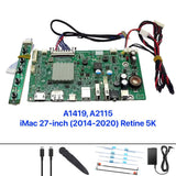
What's in the Kit
- Display Driver Board (main controller)
- Power/Inverter Board
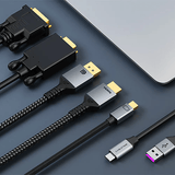
- eDP display cable
- DisplayPort to USB-C cable (2m)
- 12V 5A–8A Power Adapter
Tools You'll Need
- 2x Suction cups
- T10 Torx screwdriver
- T8 Torx screwdriver
- Plastic spudger / pry tool
- Double-sided tape
Part 1
Disassembly
Confirm your iMac model


Confirm you have an iMac 27-inch (2009–2011) — check the label on the bottom of the stand. Place the iMac face-up on a padded surface.
Remove the glass panel

Place two suction cups on the lower corners of the glass panel. Pull firmly and evenly to break the magnetic seal. Tilt the glass forward and set it face-down on a clean cloth.
LCD panel now exposed — remove the perimeter screws

With the glass removed the LCD panel is visible inside the aluminium frame. Remove the T10 Torx screws around the perimeter of the LCD (typically 8–12 screws).
SLOWLY Tilt the LCD panel forward to expose the internals

Carefully tilt the LCD panel toward you — do not pull it too far as it is still connected by cables. Rest it at about 45 degrees to access the connectors underneath.
Disconnect the display data connector from the logic board

Locate the display data connector on the logic board (circled in photo). Press the locking tab and gently pull the connector straight out.
Disconnect the backlight cable

Disconnect the flat ribbon backlight cable from the GPU board (circled). Flip up the locking tab before pulling to avoid damage.
Disconnect the LCD power cable from the logic board

On the back of the LCD panel, flip up the small locking tab on the eDP connector and carefully slide the cable free.
Disconnect the LCD sensor cables from the logic board

Disconnect the remaining cables from the area of the logic board labelled LCD (circled). These are the backlight power and LCD power connectors.
Fully remove the LCD panel and glass

With all cables disconnected, lift the LCD panel fully out of the chassis and set it aside. You should now have three items: chassis, glass panel, and LCD panel.
Strip all internal components from the chassis

Remove the logic board, hard drive, optical drive, power supply, fans, and all remaining hardware. You are stripping the chassis to an empty shell.
Identify the bracket to keep — and the cable routing hole


The black bracket at the bottom-right (circled) must stay — it is the stand attachment mechanism. Also note the circular cable hole where the stand meets the chassis — this is where your USB-C and power cables will exit.
Empty chassis — ready for the driver board


The chassis is fully stripped with only the stand mounting bracket remaining (circled). You are ready to install the driver board.
Part 2
Driver Board Installation
Connect the new eDP cable to the LCD panel


Lay the LCD panel face-down on a soft cloth. Align the new eDP cable (from the kit) with the eDP connector on the back of the LCD. Insert it straight in and press the locking tab flat to secure it. Give it a gentle tug to confirm it is locked.
Note: do not remove the LCD back bracket

There is a black plastic bracket on the LCD back labelled DO NOT REMOVE THIS PART. Leave it in place — it is a structural bracket for the LCD assembly.
Mount the driver boards on the back of the LCD panel


Using double-sided tape, mount both driver boards to the upper-left section of the LCD back:
- Main controller board (left) — USB-C input, HDMI port, button ribbon connector
- Power/inverter board (right) — connected via the red/yellow/black power harness
The LCD has an "UP" arrow — orient the boards so all ports are accessible when reinstalled in the chassis.
Lower the LCD (with boards attached) into the chassis

Carefully lower the LCD panel — with boards attached — back into the iMac chassis. The driver boards sit at the top of the chassis interior. Ensure no cables are pinched.
Connect all cables to the driver board

Connect the following to the main controller board:
- The eDP ribbon cable from the LCD into the eDP port on the controller board
- The power barrel connector from the power harness into the DC input
- The button controller ribbon cable (if your kit includes one)
Also connect the USB-C cable into the USB-C port — this will be routed out through the stand.
Part 3
Cable Routing & Reassembly
Route cables out through the stand hole

Feed the USB-C cable and power cable through the circular opening at the base of the chassis. This keeps the cable run clean. The button controller board tucks neatly into the gap near the stand.
Connect the 12V power adapter

Plug the included 12V 5A–8A power adapter into the power cable. The adapter sits on your desk behind the stand. Do not power on yet.
Reinstall the LCD screws then replace the glass panel

Reinstall the T10 Torx screws around the LCD perimeter. Then align the glass panel over the magnetic frame and press firmly around all edges until it snaps back into place.
Part 4
First Power-On & Language Setup
Connect and power on
Connect the USB-C end of the included cable to your MacBook or PC's Thunderbolt / USB-C port. Plug in the power adapter. The display should turn on and be detected automatically as a 2K external monitor.
On macOS go to System Settings → Displays. On Windows go to Display Settings → Detect.
Change the OSD language to English (if needed)


If the OSD menu defaults to Chinese, switch to English:
- Press the Menu button on the controller
- Navigate to the gear/settings icon
- Select Language (globe icon)
- Select English
- Press confirm to save
Reference
Troubleshooting
| Issue | Likely Cause | Solution |
|---|---|---|
| No image on screen | Loose eDP or power cable | Re-seat the eDP cable at both ends |
| Monitor not detected | USB-C port lacks DisplayPort Alt Mode | Try a Thunderbolt port |
| Screen flickers | Loose power connection | Check the DC barrel connector |
| Very dim image | Backlight cable not seated | Re-seat the backlight power connector |
| OSD in Chinese | Default language | Follow Step 22 above |
Reference
Button Controller Guide

Installation Complete!
Your iMac 27" is now a fully functional 2K external monitor. Camera and speakers are no longer active — but the display looks incredible.
Buy the Display Driver Board →Questions? Email us at helpdesk@macfixit.com.au
Important: where to place the double-sided tape
When you mount the driver board, the double-sided foam tape must only touch a bare, flat area of the board. If the tape is placed over the pin headers, solder pads or components, it can bridge the contacts and cause a short circuit — which can permanently damage the board. Take a moment to position the tape correctly before pressing it down.


The board pictured is a sample from our workshop — yours may look slightly different depending on your model, but the same rule applies to every board: keep the tape clear of pins, solder pads and components.